

Webcam
Webcam serves as the primary visual sensor in this project. Connecting it with RPi, we can process the image gathered by Webcam with OpenCV. First, after designating the color of the ball, we use a mask with the designated color to recognize the direction of the ball. Then, by calculating the x coordinate of the center point of the color, we can obtain the approximate position of the ball in the frame. The next step is to use this information to perform visual feedback and steer the robot towards the ball.
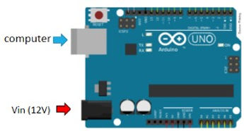
Arduino UNO
Arduino was responsible for controlling the movement of the robot and the actions of the servos. The RPi will send signals to Arduino whenever the robot needs to act differently.
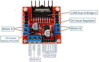
H-Bridge
An H-Bridge circuit contains four switches with the motor at the center forming an H, closing two particular switches at the same time reverses the polarity of the voltage applied to the motor. This leads to a change in the direction of the motor.
By controlling the duty cycle of the PWM signals, we can also control the angular velocities of the two wheels.
PCA9685
PCA9685 is an I2C-controlled PWM driver that can control up to 16 servos. Since we need to control 3 servo motors and 2 wheel motors, there would be insufficient output ports on the Arduino. Therefore, with the extension of PWM outputs on PCA9685, we don't need to worry about running out of GPIOs on the Arduino board.

Raspberry Pi3
The RPi is responsible for image processing and decision-making for the robot's movement. Using Raspbian as the operating system, we became familiar with operating on Linux-based systems.
To get information from the website and communicate with Arduino, we used Python as our main programming language.

Features
Eye-in-Hand
In order to see all of the balls at the initial position, the elevation angle of the Webcam needs to be parallel to the horizon. However, when the robot becomes near to the designated ball, the webcam needs to look down and focus on the ball to approach the ball precisely.
Therefore, we attached the webcam onto a 1 DOF robot arm to adjust the angle of the camera when the robot comes near the ball.

Visual Servo Feedback control

From image processing, we can obtain the center of the ball in the image. Then, we use it as the reference direction of the robot. By substracting the x coordinate of the center of the ball with the image center, we can obtain the error. Using the information of this error, we multiply it by a constant to control the two wheel velocities of the car. In other words, when the center of the ball is in the right half side of the image, we need to make the robot turn right to approach the ball. As a result, if error > 0, the right wheel will be stopped, and the left wheel will go at a speed of Kp x |error|. This can ensure the robot turning slower when the center of the call becomes closer to the center of the image. On the other hand, if the error < 0, the left wheel won't move, and the velocity of right wheel becomes Kp x |error|. Moreover, when the center of the ball enters the safety region, the robot will keep moving forward with a constant speed. Finally, the ball can be captured by the robot precisely.

Obstacle Avoidance
We used three ultrasonic sensors to detect obstacles. First, we let the distance measured by the ultrasonic sensor at the front called dF, the distance at the right called dR, and the distance at the left called dL. When the obstacles is at the front (dF is less than 18 cm), it will first compare dR and dL. If dR is greater than dL, the robot will go right to avoid the obstacle; On the other hand, if dL is greater, the robot will go left. This ensures the robot to avoid obstacles whenever there is walls on the side.

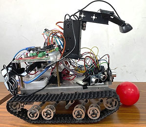
Pinball mechanism
Since we need to deliver the ball to the goal and put it into the selected section, we come up with an idea that simplifies the procedure. Considering our robot has a relatively high chassis, the ball can go under the robot without any difficulty. Therefore, we don't need to worry about capturing the ball with any extra mechanisms. The robot can just simply run through the ball and take it to anywhere it goes. As a result, we designed a mechanism that can launch the ball when it arrives the destination. The concept of this mechanism is similar to that of a pinball machine. When the mechanism opens, the two bars attached to the servos will hit the ball and make it come out of the chassis. In order to make sure the ball won't roll out during the movement of the robot, we used duct tapes on the bars to increase the friction and stop the ball from rolling.


Website and MySQL database
To communicate with the robot, we designed an user interface website that is constructed by HTML and PHP.


The PHP is responsible for connecting to the database and change the status to the selected colors. Then, it will send back signals to initiate the motion of the robot.
Python
Finally, the python file will connect to the database and determine the movement of the robot.

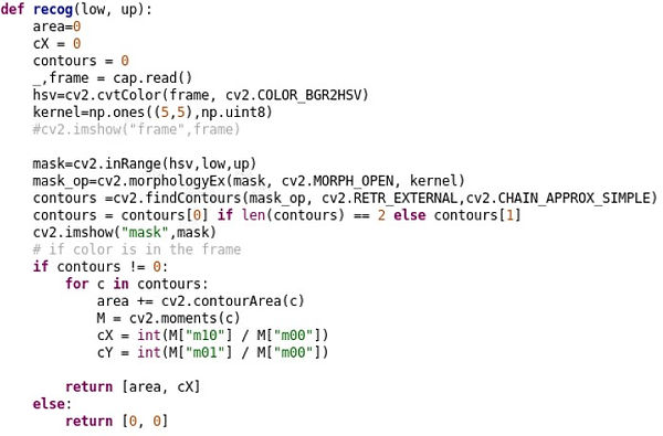
With OpenCV, we can process the image and find the contour of the ball by using a corresponding color mask. Then, we will calculate the total area of this color in the image and find the coordinate of the center in the image. Next, we can use this information for visual feedback to control the robot heading the designated direction.
Code files
Implementation video

Delivery Robot
Overview
The outbreak of coronavirus has led to many changes in our lives. One significant change is the increasing demand for food and medical delivery. This situation results in the need for an autonomous robot delivery system. Robotic delivery services can promise contactless delivery while reducing the cost of labor forces.
In this project, we developed a robotic delivery system that can deliver the designated object to the desired destination.
Using a website to specify the target ball color and the goal position color, the mobile robot will approach the target ball by using visual servo techniques. Then, the robot will carry it across the field while performing object avoidance. After approaching the goal positions, the robot will stop and look around for the designated color. Once the target is in sight, the robot will quickly move forward and launch the ball into the goal. If the ball enters the goal successfully, the robot will send back a message to the client through the app.
Skills & Abilities
-
System integration
-
Programming (Python & C/C++)
-
Visual-feedback control
-
Familiar with Linux
-
Image processing and color recognition (OpenCV)
-
Mechanisms design and fabrication
-
Circuitry and electrical wiring
Functional Requirements
-
Allow a client to place an order for a ball with specified color through an app
-
Deliver the ball to the designated position
-
Send back a success message to the client after accomplishing the mission
-
Avoid static obstacles
Bonus
-
Can be controller by a remote controller
Hardware setup
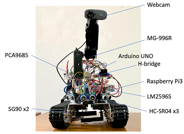
Components
-
Webcam
-
MG-996R
-
Arduino UNO
-
H-bridge
-
PCA9685
-
Raspberry Pi3
-
LM2596S
-
HC-SR04 (x3)
-
SG90 (x2)
Features
-
Eye-in-hand
-
visual servo feedback control
-
Object avoidance
-
Pinball-mechanism
-
MySQL database
Block diagram
