


Robotic Arm
Overview
In this project, the goal is to develop an Intelligent sensing and precise cultivating system for tomato growth in greenhouses. We intend to use Chlorophyll Fluorescence Imaging to determine if the plant is having water stress or not. However, the process of Chlorophyll Fluorescence Imaging is time consuming. Therefore, by integrating it with a robotic arm, we can automate the process and increase the efficiency.
Skills & Abilities
-
Solidworks
-
Matlab & Simulink motion planning
-
circuitry and electrical wiring
-
Mechanisms design and fabrication
-
key components selection

Materials and Methods
Chlorophyll Fluorescence Imaging
In this project, the goal is to develop an Intelligent sensing and precise cultivating system for tomato growth in greenhouses. By detecting water stress in a plant, we can determine if the plant needs water or not and use a precise irrigation system to water the plant. However, there are several approaches to detect the water stress. The non-destructive testing method we adopted is called the Chlorophyll Fluorescence Imaging.

During the process of photosynthesis, the plant will emit fluorescent light as a source of energy dissipation. Through Fluorescence imaging, we can capture the intensity of the fluorescence emitting from the plant and use this data to predict the efficiency of the photosynthesis within the plant, which is directly related to the amount of water the plant can absorb. Therefore, we can utilize this information to learn about if the plant is having water stress or not.

Robotic arm design
The robotic arm have to be agile enough to capture the image of a leaf while avoiding other leaves and branches. Since the robotic arm will combine with a mobile robot in the end to autonomously detect all of the plants in a greenhouse, we have an extra degree of freedom from the mobile robot. Therefore, I designed the robotic arm to have 5 degree of freedom (DoF). After I've drawn the prototype of the arm, I analyzed how much torque is required for each joint to decide the specifications for the motors. Calculated from the end effector to the base joint, the calculations can be seen below.

Joint 5

Joint 4

Joint 3

Joint 2
To maintain a smooth movement and high precision while having relatively low cost, I decided to use
DC brushed servo motors. The details for the motors can be seen in the following table.

3D printing and Assembling the Robotic arm
After having an initial design, I started printing the components of the robot. It took me a lot of time arranging the schedule for the 3D printers. Also, the results may sometimes be printed out badly, so I have to rearrange the schedule and re-print them. After spending a month printing and assembling the robot, I finally finished the mechanism of the robot.

Circuit Design and Wiring
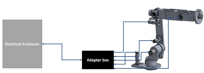
Since the robotic arm will eventually combine with a mobile robot, I designed a electrical enclosure which contains the motor drivers and the control card. The following is the electrical schematic for the electrical enclosure.

Also, in order to make sure the robot and the electrical enclosure have a reliable and unified connection, I also designed a intermediate adapter box. This adapter can ensure the wires on the robot arm have a mechanical attachment and won't get disconnected easily while the robot is operating.
The wires were covered with heat shrinking tubes to make sure they won't get messy. Inside the adapter box, the wires were labeled and colored so I won't get confused when soldering them to the pins on the connecter.

[Inside the box]

[Wiring of the robot]
Simulation
Creating the URDF model
To simulate the robot arm and visualize it, Unified Robot Description Format (URDF) for the robot must be created. The URDF file can be used in Simulink, ROS, and several other simulation tools. After I have used Solidworks to draw the CAD file of the robotic arm, I tried to create the URDF file using a URDF Exporter package in Solidworks. The following is the URDF model of the robotic arm.

Matlab & Simulink


This part will focus on the path planning and trajectory tracking for the robotic arm. The reference trajectory was set to be a "N" shape, which is shown in red dotted line. After the reference points were decided, the simulink model will use the inverse kinematics of the robot to determine the joint parameters. Then, the robot will start moving and try to track the trajectory. The actual trajectory of the robot is displayed as the black line in the figure
